


What is a Thermal Overload Relay? How It Protects Electric Motors
In manufacturing plants, commercial HVAC systems, and automated workshops, three-phase asynchronous motors drive critical equipment—from high-pressure water pumps and industrial compressors to heavy conveyor belts and ventilation arrays. However, unexpected operational stresses such as mechanical bearing friction, impeller blockages, sustained voltage drops, or sudden phase imbalances force motors to draw current well above their rated capacity.
Continuous exposure to overcurrent rapidly overheats internal stator windings, degrades enamel insulation, and ultimately results in catastrophic motor burnout. The foundational safety component engineered to prevent thermal destruction in electric motors is the thermal overload relay. In this guide, we examine what a thermal relay is, explore how it operates, analyze its coordinated function alongside power contactors, and outline best practices for accurate current calibration.
What is a Thermal Overload Relay and How Does It Work?
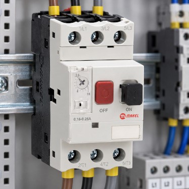
A thermal overload relay is an electromechanical protection device designed to monitor motor current, detect abnormal temperature rises generated by sustained overloads, and interrupt the control circuit before winding insulation is compromised.
Its internal operation relies on the mechanical deflection of bimetallic strips:
-
Bimetal Strip Elements: Inside the unit, three independent bimetallic strips correspond to each power phase. Each strip consists of two bonded metals with differing thermal expansion coefficients, wrapped in an insulated heater winding carrying the motor line current.
-
Thermal Deflection: As current flows through the heater coils, heat builds up. When current exceeds rated operational limits over time, the metals expand at unequal rates, causing the strips to bend mechanically toward a release mechanism.
-
Trip Slide Activation: Once deflection reaches a predetermined threshold, the bimetal strips push against an internal trip bridge.
-
Auxiliary Contact State Change: The relay's normally closed auxiliary contact (NC - 95-96) trips open instantly, de-energizing the connected contactor coil and disconnecting main power to the motor. Simultaneously, the normally open contact (NO - 97-98) closes, triggering an alarm beacon or sending an alert signal to a central monitoring system.
Protection Against Phase Loss (Differential Trip Mechanism)
In three-phase power networks, one of the most destructive failure modes is single-phasing (the complete loss of one phase due to an upstream blown fuse or severed conductor).
When an operating motor loses a phase, it continues running on the remaining two phases while attempting to deliver the same mechanical shaft output. This forces the active windings to draw up to 1.73 times their standard rated current, triggering rapid localized overheating. Modern thermal overload relays feature integrated differential protection; the internal mechanical slides detect unequal deflection between phases, accelerating the trip sequence to isolate the motor before winding burn occurs.
Thermal Relay Wiring and Coordination with Contactors
Thermal overload relays do not contain internal arc chutes or high-capacity power contacts capable of breaking primary short-circuit currents on their own. Instead, they are engineered to integrate directly with a magnetic contactor:
-
Power Circuit Connection: The copper prongs extending from the top of the thermal relay clamp directly into the load terminals (T1-T2-T3) of the contactor. The bottom terminal lugs (2T1, 4T2, 6T3) connect directly to the motor lead wires.
-
Control Circuit Integration: The relay's NC contact (95-96) is wired in series with the contactor's control coil supply line (A1 or A2). When an overload trip occurs, this contact opens, de-energizing the coil and causing the contactor's heavy main poles to open.
-
Reset Configuration: Units feature a selectable reset selector allowing either "Manual" reset (requiring a technician to inspect the fault and press the button) or "Automatic" reset (which resets the contact once the bimetal strips cool down).
To equip your motor starter assemblies with precision tripping curves and reliable contact architecture, explore Makel's Thermal Relays Group collection.
How to Calibrate Current Settings Accurately
Incorrect current calibration leads either to nuisance tripping during routine production or failure to trip during genuine overloads. Follow these standard rules when calibrating the adjustment dial:
-
Reference Motor Full-Load Amperes (FLA): Align the rotary current dial precisely with the rated nominal current stamped on the motor's nameplate (), rather than the contactor's maximum thermal rating.
-
Inverse-Time Tripping Curves: Because bimetal deflection depends on accumulated thermal energy, thermal relays naturally possess inverse-time delay characteristics (higher currents trip faster, while brief inrush current during initial startup passes without tripping). Never deliberately dial the setting higher just to compensate for momentary starting spikes.
-
Ambient Temperature Compensation: Because ambient panel temperatures influence bimetal strip movement, select relays featuring built-in ambient temperature compensation (typically rated between -5°C and +40°C) to maintain consistent trip timing.
Protecting Critical Industrial Investments
Electric motors represent major operational and capital investments. A burned-out motor incurs substantial rewinding costs, unexpected system downtime, and production loss across industrial lines. Installing matched, precision-calibrated thermal overload relays eliminate these operational vulnerabilities. Engineered to comply with international low-voltage standards, Makel's switchgear components provide robust protection, maintaining equipment continuity across commercial and industrial motor installations.