













What is a Motor Protection Circuit Breaker? Working Principles and Selection Guide
In manufacturing facilities, commercial facilities, and mechanical rooms, electric motors run critical infrastructure from industrial air compressors and high-volume ventilation fans to circulation pumps and automated conveyor lines. However, electric motors are vulnerable to electrical anomalies, including direct short circuits, sustained overloads, phase loss, and locked rotor conditions.
A motor failure incurs rewinding costs and triggers unplanned downtime across production lines. The specialized low-voltage switchgear engineered to combine overload, short-circuit, and phase-loss protection in a single, compact housing is the motor protection circuit breaker (MPCB, also referred to as a manual motor starter). In this technical guide, we break down what an MPCB is, analyze how its dual-trip mechanism works, contrast it with standard fuses and thermal relays, and explain how to calculate accurate sizing for motor installations.
What is an MPCB and How Does It Work?
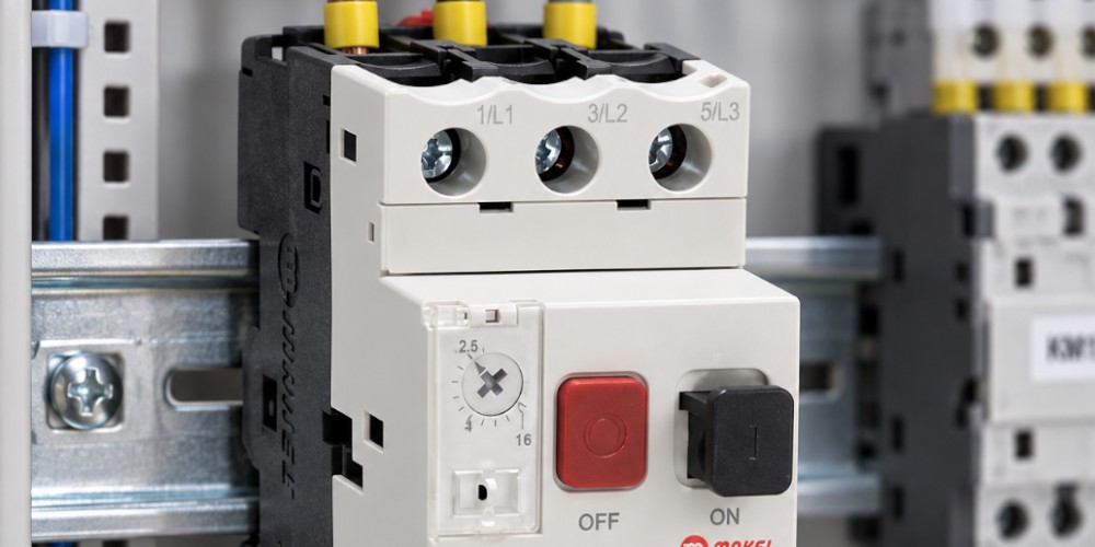
A motor protection circuit breaker is a specialized electromechanical protection device installed in the main branch circuit feeding an electric motor. It provides both thermal (overload) and magnetic (short-circuit) protection, while also serving as a manual disconnecting switch.
Inside its housing, an MPCB integrates two trip mechanisms:
-
Thermal Protection (Bimetallic Strip): When a motor encounters mechanical resistance or operates under phase imbalance, it draws continuous overcurrent. This current heats an internal bimetallic strip. As the unequal thermal expansion forces the strip to deflect, it trips the internal release latch, opening the main power contacts and isolating the motor before its insulation burns.
-
Magnetic Protection (Electromagnetic Solenoid): In the event of a direct short circuit or line-to-ground fault, fault currents surge through the circuit. An internal electromagnetic coil detects this instantaneous spike and triggers an armature in milliseconds. The high-energy fault current is safely directed into internal arc chutes and extinguished, protecting cabling and motor windings from physical destruction.
Additionally, MPCBs feature integrated push-button or rotary switches (Start/Stop), allowing operators to safely isolate or manually start motors directly at the control cabinet.
MPCB vs. Miniature Circuit Breaker vs. Thermal Overload Relay
Control panel builders frequently compare MPCBs with conventional circuit breakers and thermal relays. While their functions overlap, their operational boundaries are distinct:
|
Parameter |
Miniature Circuit Breaker (MCB) |
Thermal Overload Relay |
Motor Protection Circuit Breaker (MPCB) |
|
Overload Protection |
Fixed (non-adjustable) |
Adjustable current dial |
Adjustable current dial |
|
Short-Circuit Protection |
Standard breaking capacity |
None |
High breaking capacity () |
|
Direct Contact Breaking |
Breaks main contacts |
Requires a series contactor |
Breaks main power contacts independently |
|
Phase Loss Sensitivity |
None |
Yes (Differential slide) |
Yes (Differential slide) |
|
Inrush Current Handling |
General Type C/D curves |
Motor-rated delay curve |
Motor-rated start curve (Class 10) |
A thermal overload relay cannot clear short circuits on its own and requires a dedicated contactor to interrupt line power. In contrast, an MPCB handles short-circuit currents and isolates the branch circuit independently without auxiliary devices.
How to Select the Right Motor Protection Circuit Breaker
Proper motor protection circuit breaker selection ensures the breaker withstands high inrush starting currents while remaining responsive to sustained overcurrents:
1. Identify Motor Full-Load Amperes (FLA)
Refer to the motor rating plate to identify its rated power (kW/HP), rated voltage (e.g., 230V or 400V AC), and nominal operational current ().
2. Match the Adjustable Setting Range
MPCBs feature an integrated rotary calibration dial providing an adjustable current window (e.g., 4.0A – 6.3A, 9.0A – 14.0A). The motor's full-load running current must fall squarely within this range. Calibrate the dial precisely to the motor's nominal current stamped on its nameplate.
3. Verify Ultimate Short-Circuit Breaking Capacity ()
Ensure the breaker's rated breaking capacity (e.g., 50kA or 100kA at 400V) meets or exceeds the prospective short-circuit current calculated at that specific distribution board location.
For robust motor branch circuit protection with high breaking capacities and space-saving dimensions, explore Makel's Motor Protection Switches Group.
Compact, Complete Defense for Electric Motors
Motor protection circuit breakers combine the roles of an isolator switch, thermal overload relay, and short-circuit breakers into one modular device. This reduces panel space requirements, simplifies control wiring, and cuts assembly labor costs. Engineered with fast-acting magnetic coils and calibrated bimetals, a quality MPCB safeguards industrial motor assets against thermal degradation, line-to-line faults, and phase failures. Makel's low-voltage switchgear delivers reliable, code-compliant motor control for both industrial automation panels and building service networks.