





What is a Contactor? Function, Types, and Selection Guide
In modern electrical installations and industrial automation environments, controlling high-current equipment safely and remotely is an essential requirement. Switching heavy electrical loads such as large electric motors, high-bay lighting arrays, capacitor banks, and industrial heating elements directly with manual mechanical switches poses serious arcing hazards and rapidly wears out switch mechanisms.
The primary electromechanical component engineered to manage, switch, and automate high-power electrical circuits safely is the contactor. In this technical guide, we break down what a contactor is, analyze how it operates, examine the key differences between contactors and relays, and outline the core criteria for accurate contactor selection.
What is a Contactor and How Does It Work?
By technical definition, a power contactor is an electrically controlled electromechanical switch designed to open and close power circuits carrying heavy loads. Unlike circuit breakers, contactors are not designed to interrupt short-circuit currents on their own; instead, they serve as high-endurance switching devices that operate frequently under normal and operational overload conditions.
The operational principle relies on electromagnetic induction:
-
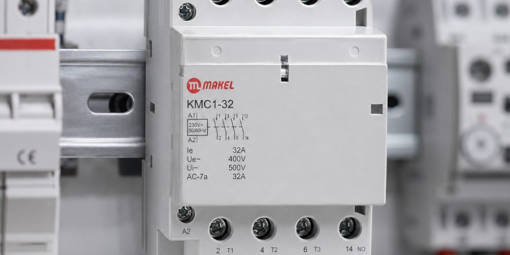
Coil Terminals (A1 – A2): The control circuit connects directly to these terminals. When an appropriate control voltage (e.g., 24V DC, 110V AC, 230V AC, or 400V AC) energizes the internal coil, it establishes a magnetic field.
-
Electromagnetic Core and Armature: This magnetic field pulls a movable iron core (armature) toward the stationary core.
-
Main Power Contacts Closing: The mechanical motion of the armature forces the main high-current contacts (L1-L2-L3 to T1-T2-T3) shut simultaneously, supplying electricity to the connected equipment (such as an induction motor).
-
Circuit Interruption: When control voltage to the coil is de-energized, an internal return spring forces the armature back to its resting position, opening the main contacts and cutting power instantly and safely.
Contactor vs. Relay: What Are the Key Differences?
Because both devices utilize an electromagnetic coil to actuate internal contacts, contactors and control relays are often confused. However, they serve distinct operational roles:
|
Parameter |
Control Relay |
Power Contactor |
|
Current Carrying Capacity |
Generally limited to 5A – 16A |
Ranges from 9A to hundreds or thousands of Amps |
|
Arc Quenching Chambers |
Not present |
Features built-in arc chutes to extinguish switching sparks |
|
Contact Architecture |
Typically control/auxiliary contacts only |
Heavy main power poles + auxiliary contacts (NO/NC) |
|
Primary Applications |
Signal processing, automation cards, interlocks |
Three-phase motors, pumps, transformers, main distribution |
Contactor Types and IEC Utilization Categories
Selecting the correct contactor depends on the electrical profile of the load being switched. The International Electrotechnical Commission (IEC 60947-4-1) classifies AC contactors into standardized utilization categories:
-
AC-1 (Non-Inductive or Slightly Inductive Loads): Tailored for resistive loads where power factors are close to unity, such as industrial resistance heaters, electric ovens, and general non-inductive lighting.
-
AC-2 (Slip-Ring Motors): Used for starting, plugging, and inching slip-ring induction motors.
-
AC-3 (Squirrel-Cage Induction Motors - Normal Duty): The industry standard category for starting squirrel-cage motors and shutting them down during full running speed (e.g., HVAC compressors, conveyor belts, water pumps, exhaust fans).
-
AC-4 (Squirrel-Cage Induction Motors - Severe Duty): Designed for demanding operations involving rapid plugging, reversing, and continuous inching/jogging (e.g., cranes, hoists, and heavy machine tools).
For long service life and high electrical endurance across industrial panels and commercial installations, explore Makel's Contactors Group portfolio.
How to Select the Right Contactor
Undersizing a contactor or misjudging duty cycles can cause contact welding, severe contact pitting, coil burnout, and motor failure. Follow these critical steps for reliable sizing:
-
Motor Power and Full-Load Current (kW and Amperes): Determine the continuous operating current () and starting (inrush) current of the load to ensure the contactor's main poles accommodate the load profile under the designated utilization category (e.g., AC-3).
-
Control Coil Voltage: Match the coil voltage rating (A1-A2) strictly with your panel's control circuit supply (e.g., 24V DC for PLC systems, 230V AC for conventional control networks).
-
Operating Frequency (Cycles Per Hour): Heavy cycling requires stepping up to a contactor with higher mechanical and electrical durability to prevent premature failure.
-
Overload Protection Coordination: Pair the contactor output with a matched thermal overload relay or motor protection circuit breaker (MPCB) to shield the motor from phase loss and sustained thermal overcurrents.
The Foundation of Safe Power Switching
Managing heavy industrial loads demands hardware engineered to eliminate arcing hazards, ensure safe remote operation, and withstand repetitive mechanical duty. Utilizing contactors equipped with durable, silver-alloy contacts and rapid arc suppression guarantees uninterrupted performance across your facility. Makel's internationally compliant contactor solutions deliver robust power management and long-term reliability for both commercial and industrial infrastructure.


