


10 Common Errors in Electrical Installations and Correct Application Methods

Electrical installation is the most critical infrastructure system determining both the safety and the lifespan of a structure. Small errors made during field applications lead to major malfunctions or fire risks in the future. It is of great importance for technical personnel and electricians to notice these errors in advance to establish a sustainable system. This guide explains the 10 most common technical errors encountered in the field and their correct solution methods.
1. Insufficient Cable Cross-Section Selection
The harmony between current carrying capacity and cable cross-section is vital in electrical installations. Using a cable thinner than required by the load causes the line to overheat.
- Faulty Application: Pulling low cross-section cables for high-power devices to reduce costs.
- Correct Method: The cable cross-section must be determined according to the total power on the line and voltage drop calculations. For example, copper conductors with a minimum cross-section of 2.5 $mm^2$ should be used for socket branch lines.
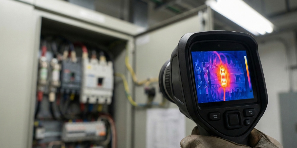
2. Loose Terminal and Connector Connections
Looseness at connection points is the most common cause of fires in electrical installations. Loose screws lead to arcing and overheating.
- Faulty Application: Not tightening the screws at fuse inputs or terminals with sufficient torque.
- Correct Method: All connections must be tightened using appropriate torque screwdrivers. During periodic maintenance, the tightness of connections should be checked with a thermal camera.
3. Incorrect Selection or Absence of Residual Current Devices (RCD)
A residual current circuit breaker is mandatory for the safety of life and property. However, the mere existence of this device is not enough; the type selection is also important.
- Faulty Application: Using standard Type AC relays in places where electronic devices are concentrated.
- Correct Method: Type A or Type B residual current devices should be selected for sensitive electronics and inverter devices. Type S (Selective) relays should be preferred at the main panel for system continuity.
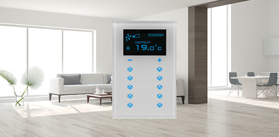
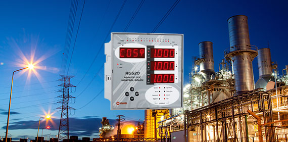
2. Real-Time Analysis and Monitoring Accuracy
As mentioned in the energy monitoring data , measuring consumption with high precision is essential for identifying these installation errors. Real-time data helps detect if a connection is failing or if a phase is unbalanced before it causes a fire.
4. Non-Compliance with Cable Color Coding and Labeling
Chaos in the panel arrangement extends the response time during a malfunction and increases the risk of faulty connections.
- Faulty Application: Using the same color cable for all lines or the absence of terminal labels.
- Correct Method: Standard color codes (Phase: Brown/Black/Grey, Neutral: Blue, Earth: Yellow-Green) must be strictly followed. Both ends of every cable should be numbered.
5. Incorrect Grounding Applications
The grounding system is the safety insurance of the installation. High grounding resistance prevents protection devices from operating.
- Faulty Application: Connecting the grounding line only to metal pipes or using insufficient electrodes.
- Correct Method: Grounding resistance (spreading resistance) must be measured and remain within regulatory limits. Grounding rods and conductive plates must be used at appropriate depths.
6. Excessive Cable Density and Disorder in Panels
Cable clutter inside the panel prevents heat dissipation and makes technical intervention difficult.
- Faulty Application: Cables overflowing out of ducts and blocking the front of the fuses.
- Correct Method: Cables should be organized within appropriately sized cable ducts. Sufficient space must be left for air circulation inside the panel.
7. Neglecting the Use of Ferrules and Lugs
Inserting multi-strand cables directly into a terminal causes some of the conductor wires to remain outside or be crushed.
- Faulty Application: Twisting cable strands and placing them directly under the screw.
- Correct Method: An insulated cable ferrule or cable lug of appropriate size must be pressed onto the ends of multi-strand cables.
8. Running Power and Data Cables through the Same Duct
Electrical cables create a magnetic field around them. This field causes signal distortions in cables carrying data.
- Faulty Application: Carrying 220V energy lines and CAT6 or fiber optic cables adjacent to each other within the same duct.
- Correct Method: A physical distance must be left between power and data cables. If they pass through the same tray, a metal divider (separator) must be used.
9. Incorrect Determination of Fuse Amperage
A fuse is intended to protect the cable it is connected to. A fuse selected larger than the carrying capacity of the cable invites fire.
- Faulty Application: Installing a 25A fuse on a lighting line using 1.5 $mm^2$ cable.
- Correct Method: The fuse current value must be lower than the maximum current carrying capacity of the conductor it protects. A hierarchical ranking should be made according to the selectivity rule.
10. Insulation Errors and Exposed Conductors
Cables with damaged insulation or exposed live ends pose a direct risk of electric shock and short circuits.
- Faulty Application: Closing junction points haphazardly with only electrical tape.
- Correct Method: Appropriate junction terminals or heat-shrink tubing should be used at connection points. Insulation resistance tests (Megger test) should be performed throughout the installation.
Field Application Checklist
You can use the following table as a guide to measure application quality:
|
Control Point |
Sign of Faulty Application |
Technical Correct Application |
|
Connection Ends |
Bare copper visible outside the terminal |
Use of ferrules and full insulation |
|
Internal Panel Order |
Hanging, unbundled cables |
Use of cable ties and ducts |
|
Color Standard |
Using black/red for the neutral line |
Blue colored neutral conductor |
|
Grounding |
Leaving the ground line empty in the socket |
Continuous ground line connection |
|
Cable Passages |
Cable rubbing against sharp metal corners |
Use of glands and rubber gaskets |
Technical Safety and Long-Lasting Installation
Preventing these 10 common errors in electrical installations ensures the safety of the installation and reduces maintenance costs. Compliance with correct material selection and technical standards increases the energy efficiency of enterprises. Modern panels and smart measurement systems can detect some of these malfunctions before they even occur.
Every connection in your installation is only as strong as the weakest link in the system. Therefore, it is mandatory to carry out all applications in accordance with engineering standards and local regulations.


